

STONES SOUND STUDIO
 |
 |
Application note for Peerless XLS 10" subwoofer drive units Introduction: The following is an application note of how to use the Peerless XLS family of subwoofer drive units. The application note is meant as a starting point and as inspiration for the designer who wishes to build a subwoofer using a Peerless XLS driver. The drivers mentioned in this document are all just for reference as Peerless has a broad range of specially developed products to suit special requirements. Peerless XLS subwoofer family: The Peerless XLS family consists of a range of drivers especially developed for the high performance subwoofer application. The goal with the design has been to produce drivers with an unexcelled long excursion performance with low distortion. Using Strontium Ferrite Magnets and Finite Element Analysis to optimise the iron circuit, high levels of BL have been obtained. With the high BL available Peerless has been able to design drivers with a high moving mass and low fs but without high Qt and low sensitivity. This means that the range of drivers will work especially well in small vented or passive radiator cabinets. Mechanically the subwoofers offer a strong base, which will provide many years of high performance bass reproduction. The aerodynamic cast aluminium frame supports the vented Nomex spider and rubber surround for a heavy-duty suspension that will not fatigue. The rigid fibre reinforced and deep impregnated cone will produce low distortion bass without coloration. Design goals: This application note will describe three different approaches to design a subwoofer with the following specifications: · Compact design with 20 litres internal effective volume. · Closed, vented or passive radiator box. · Active system with amplifier equalisation and active filters. · A Peerless 10" subwoofer will be used. · Usable frequency response down to 25 Hz at max spl above 105 dB. A closed box high performance subwoofer system using Peerless XLS driver 830452: The closed box application is not so common for subwoofers. This is mainly because the air spring behind the cone results in a high fsb for the system. The SPL from a closed box will decrease by 12 dB/oct below fsb and therefore heavy equalising is necessary to obtain what corresponds to a flat 2p anechoic response. However one important feature of the closed box concept is that the "in-room" response can be flat to very low frequencies in a normal living room. This is because there is a bass boost from the room by up to 12 dB/oct below first standing wave. Therefore one must be careful when selecting the equalisation for response. Benefits and drawbacks of closed box systems: The closed box subwoofer has some important benefits : + With low Qt drivers and small boxes a very good transient response is possible. + No port noise. + The air spring inside the box will limit excursion of the driver at low frequencies. Some of the drawbacks of the closed box system are: ÷ Heavy equalisation necessary. ÷ Excursion must be very high at low frequencies to obtain flat response. ÷ Low efficiency at low frequencies. Tuning the system: Tuning a closed box system is straightforward with a pocket calculator. Putting the 10" XLS driver 830452 in to a 20 litre box with no damping material inside results in the frequency response below when a small box loss has been incorporated. Fsb is around 40 Hz and Qtsb is around 0.34. 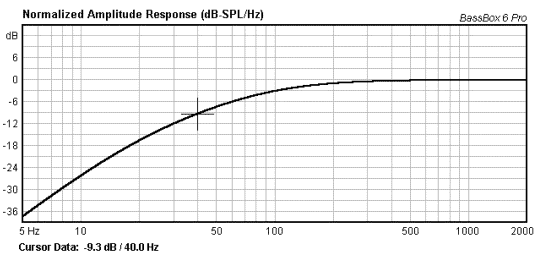 From the graph we see that it is necessary to boost by about 14 dB at 25 Hz with a low pass slope of 12 dB/oct. to achieve a flat response. The maximum sound pressure level with a 400W RMS amplifier (which is over maximum powerhandling of the driver) and no equalising will be like the following graph. 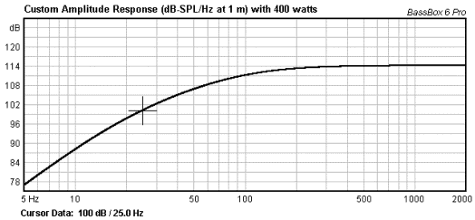 It can be seen that the maximum level at 25 Hz is only about 100 dB with 400W of amplifier power. This means that we will not be able to achieve our goal of minimum 105 dB SPL at 25 Hz without exceeding the maximum powerhandling of the driver further. Conclusion for closed box subwoofer: From the above simulations it can be concluded that even with a very powerful amplifier it is not possible to achieve the desired max SPL of 105 dB at 25 Hz. Therefore this solution is not recommended with the target specifications needed. Using a larger cabinet or counting on the bass boost of all living room environments with the boundaries contributing to amplification of the lowest frequencies the target specification can be achieved. A vented high performance subwoofer using Peerless XLS driver 830452: The vented subwoofer is a popular way to achieve high performance at a reasonable cost. Some considerations regarding the vented approach are however necessary before choosing this design. Benefits and drawbacks of vented systems: The vented system has many benefits here are a few important ones: + It is typically inexpensive. + Properly tuned results in high performance. + High efficiency at low frequencies. + Cone excursion is low at the tuning frequency. Some of the drawbacks of the vented system are: ÷ Low tuning in a small cabinet means long ports. ÷ Long ports means complex construction, which increases cost. ÷ Reduction of port noise means large cross section, which again means longer ports. ÷ Large excursion of the drive unit at frequencies below tuning. High pass filter typically needed. Tuning the vented subwofer: The basic theory of vented systems has been studied for many years and the literature is rich of articles describing the various designs possible. In this application note the box volume and driver are fixed parameters so we are only able to change the port design. Normally a large cross section of the port is recommended to avoid port noise and turbulence. Putting the 10" XLS driver 830452 in to a 20 litre box with no damping material inside results in the frequency response below when a small box loss has been incorporated. 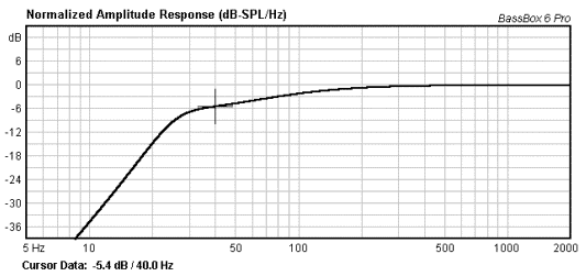 From the simulation it can be seen that the system response is down by about 5.4 dB at 40 Hz. A simple first order correction circuit in the active amplifier can easily correct this. The maximum SPL from the system with 400 W of amplifier power can be seen below: 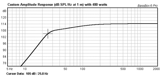 From the above simulation it can be seen that the max SPL is 105 dB at 25 Hz which means that we have achieved our goal, but we need to check that the maximum linear excursion of the driver has not been exceeded. It is normal for a vented system to have two excursion regions of importance. One excursion region is where the drive unit only is producing the SPL the second excursion region is below tuning at 25 Hz where the excursion rises rapidly. A good simulation program will be able to simulate the excursion of the drive unit. 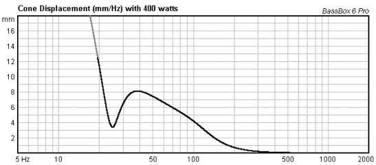 In this case the first maximum appears around 38-40 Hz. From the graph it can be seen that the design is safe in this region reaching about +- 8mm. The other excursion region is below tuning at 25 Hz where the excursion rises rapidly reaching the 12.5 mm limit at approx. 20Hz. Therefore it is recommended to limit the excursion below 20 Hz by a proper high pass filter. Choosing a sixth order vented system approach with a second order high pass filter is therefore highly recommended. The next step of the design processes it to configure the port. To keep the velocity of air in the port low is of great importance to achieve a system without port noise. Typically the air velocity should be kept below 1/10 of the velocity of sound in air or approx. 35 m/s. From the graph below it can be seen that the Ø60 mm port with 675 mm length does not fulfil this demand because the maximum is about 46 m/s with 400W: 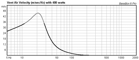 This means that a larger diameter of port is needed, which will make the port longer. Using a Ø70 mm port and 930 mm of length turns out to be a good choice: 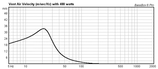 Now the velocity is below 35 m/s and if a double flared port is chosen a good result should be possible. Conclusion for the vented system: The port is long and large. This means that the port takes up some space in the cabinet, in this case using a 3 mm thick tube material will take up as much as 4.2 liters of box volume. Also including the approx. 2 litre that the drive unit occupies results in an internal box volume of 26 litre. Because the port is almost one meter long the port needs to be folded inside the cabinet or build up using a labyrinth approach. Given the design target from above it has been shown that it is possible to achieve the desired result, but the port need to be part of the cabinet design or folded to achieve the low tuning needed. It has been shown that a high pass filter for the system is highly recommended to reduce the excursion below tuning. Vented cabinet data: Total volume: 26 litre Port diameter: Ø70 mm Port length: 930 mm Tuning frequency: 25 Hz A passive radiator high performance subwoofer using Peerless XLS driver 830452: The passive radiator subwoofer is a way to achieve high performance at a reasonable cost. Some considerations regarding the passive radiator approach is however necessary before choosing this design. Low tuning of the passive radiator system s possible by using heavy moving mass in the slave. Benefits and drawbacks of passive radiators: The passive radiator system has many benefits here are a few important ones: + Low tuning in small cabinets possible. + The drive unit is more protected from large excursion at low frequency's because of suspension progressivity in the passive radiator. + Properly tuned results in high performance. + Low distortion and no port noise. Some of the drawbacks of the passive radiator system are: ÷ Sometimes a little more expensive than vented systems with similar performance. ÷ Improper tuning may result in bad transient response. ÷ The passive radiator may run out of excursion at low frequencies. Tuning the passive radiator system: The passive radiator system works in a way similar to the vented system. The impedance curve will have two peaks like the vented system. A simulation package capable of simulation of passive radiator systems is needed to simulate the system. Simulating a 20 liter nominal box with a 10" XLS slave with 400g moving mass results in the frequency response below: 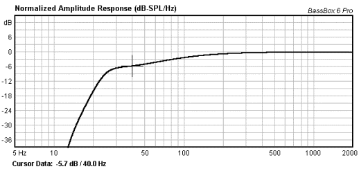 The response is similar to the vented system with approx -6 dB at 40 Hz which may be corrected by a simple first order circuit in the filter. The maximum SPL produced by the system with 400W can be seen below: 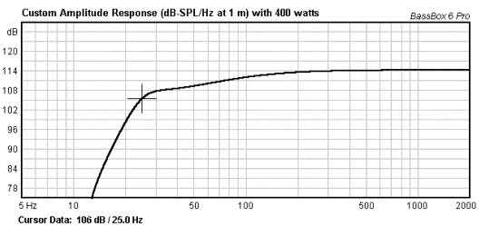 At 25 Hz the maximum is 106 dB, but we need to inspect the cone and slave excursion before proceeding with the design: 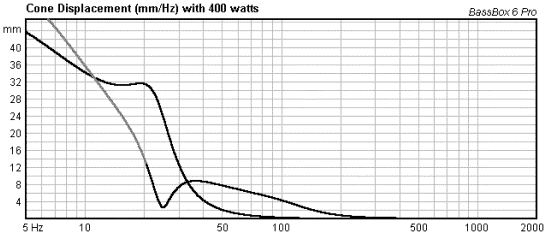 From this simulation we see that the maximum excursion of the driver is well within the limits down to 20 Hz where the linearity limit of 12.5 mm is reached. For the slave the mechanical limit of the excursion is 22 mm which occurs at approx. 26 Hz. This means that the system with a 400g moving mass on the slave is not able to produce 105 dB at 25 Hz because the slave will be overloading. If we choose a lower tuning frequency the active driver will take more of the load utilising the full potential of the active driver and reducing the needed excursion of the passive driver. 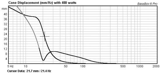 This system will need a 600 g mass on the slave to achieve the desired performance and low tuning in the 20 litre cabinet. The response of the system will be extended to 20 Hz but the efficiency is lower than the previous meaning that the response is down by about 7 dB at 40 Hz. 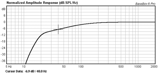 Maximum SPL in this configuration is: 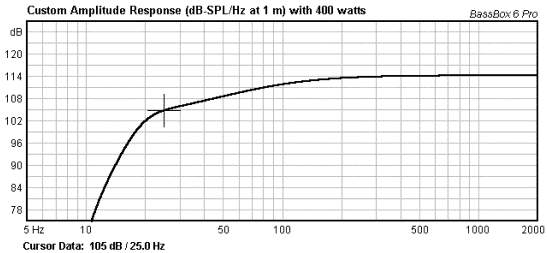 Which means that we have achieved our goal of 105 dB at 25 Hz. Conclusion for Passive radiator system: Special considerations regarding overloading of the passive radiator is needed for passive radiator systems. Careful selection of limiting circuits and tuning frequency is needed to avoid unwanted noises from the system. It has been shown that the tuning of the box is possible but that the user need to invest some time in adjusting the filters and limiters to achieve the goal. Passive radiator system data: Total volume: 20 litre XLS slave with 600g Mms Tuning frequency: 21 Hz General notes about power requirements: The XLS family has large excursion headroom and will handle high levels of power. In a typical application the amplifier will begin to clip before the driver reaches the maximum level of excursion. Low frequency amplifier clipping sometimes sounds as if the driver is overloading. Therefore it is recommended to check the amplifier output with an oscilloscope to look for clipping if the system sounds bad. Using a limiter that controls the excursion and the loading of the amplifier is highly recommended. General notes on excursion limitation: From the simulataions above it has been shown that it is possible to overload the drive units at frequencies close to and below the system tuning frequency. Therefore a high pass filter set closely below the tuning frequency where the soundpressure level decreases rapidly anyway, is highly recommended. There is no need for the drive units to overload at frequencies where the system produces no sound. A high pass filter with cut off frequency just below the tuning frequency of the system is therefore highly recommended. General notes regarding filters and noise for subwoofers to avoid localisation: It is a known fact that the human hearing looses the sense of direction for frequencies below approximately 150 Hz. We are therefore not able to tell the position of a subwoofer that only produces sound below this frequency. This means that we have freedom of placement. However, above 150 Hz the human hearing starts to localise the source. This means that if the subwoofer produce higher frequenccies than approximately 150 Hz, the user will notice the position. To avoid localisation a sharp low pass filter is needed. A 12 db/oct@150 Hz filter will only attenuate the lower midrange (300 Hz) by typically 15 dB. This means that the lower midrange will radiate from the subwoofer thus exposing the position. Conclusion and disclaimer: It has been shown that it is possible to achieve high sound pressure levels using the 10" XLS drive unit in three different configurations. Proper filters and limiters are highly recommended and this is an important but often overlooked retail in high performance subwoofers. The port design in small vented box systems is complicated because the length has to be very long. Labyrinth or tubes with bends must be used. The information contained herein is provided for the designer to have a starting point for future development on high performance subwoofers. We believe the information to be true and reliable, but there are many ways to design subwoofer systems. We cannot assume responsibility for the results obtained by others over whose methods we have no control. · Using a 24 dB/oct or even 36 dB/oct filter greatly improves the midrange attenuation. Other sources to reveal the subwoofer position is distortion and noise. Amplifier clipping or distortion will produce higher harmonics that will radiate from the subwoofer thus revealing the position The Peerless XLS woofer are very "silent" low inherent distortion and noise subwoofer drive units. This means that with careful design of amplifiers, limiters and filters the designer is able to achieve a very good result without localisation. Port noise is an other source for localisation because this noise is wideband and revealing. Port noise must be avoided. Two sources of port noise is the velocity of air in the port and turbulence at the port ends. · Using a large diameter port will reduce the velocity, but requires a longer port. · Double flared ports where both ends are flared greatly reduce turbulence at the port ends. |